
The previous page 'Complex
Resonator' explored how a resonating filter reacts to a
single-sample pulse input. Now I want to find out what a
complex integrator does with complex sinusoidal input signals. Later
on, I will figure out what interesting
filter
jobs can be done with a complex integrator on a real-only input signal.
To test the complex integrator as a filter, I wrote a separate
Max/MSP object. Instead of the user parameter decay time, I reverted to
the more direct parameter radius
again, because some relations between radius and output amplitude must
be examined.
 |
By way of complex test signal, I feed a computer-generated cosine
and
sine wave in the respective inputs of the complex resonator. Because a
(complex) sinusoid has more energy than a single sample pulse, it can
be predicted that the resonator will produce an increased output level.
The output amplitude can be easily computed by doing Pythagoras on the
real and imaginary output.
In a first test I set radius 0.9, and let the input frequency match
the filter center frequency at 200 Hz:
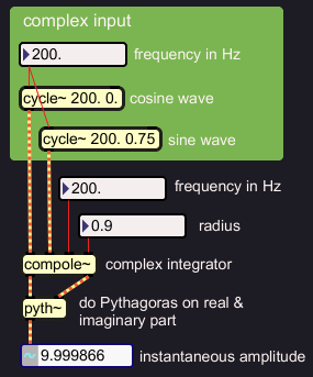 |
Oops, the output has almost amplitude 10, while amplitude 1 is unity
gain. I am happy that I did not play this over my speakers yet.
Increasing the radius, leads to further growth of the output
amplitude. Here are some values:
radius 0.9 amplitude 10
radius 0.99 amplitude 100
radius 0.999 amplitude 1000
radius 0.9999 amplitude 10000
The input amplitude seems to be magnified by:
 |
Let me first do something about these crazy amplitudes. If I
normalise the input by applying the inverse of the observed gain
factor, I expect to keep the output within the
limit of unity gain:
 |
This does the job indeed. The input sample values are multiplied by
a factor 1-radius. In the above example, that is 10, and for larger
radiuses it can mean a substantial input attenuation. Still the output
grows to a stable amplitude around 1 everytime. That is a remarkable
phenomenon. For ease of use, I incorporate this normalisation in the
object.
Now that the complex integrator input is normalised, filter
characteristics can be checked. To visualise the filter effects, I feed
complexified noise in, and plot a complex spectrum of the output. I use
linear scales for amplitude and frequency, and an example with a fairly
high filter center frequency:
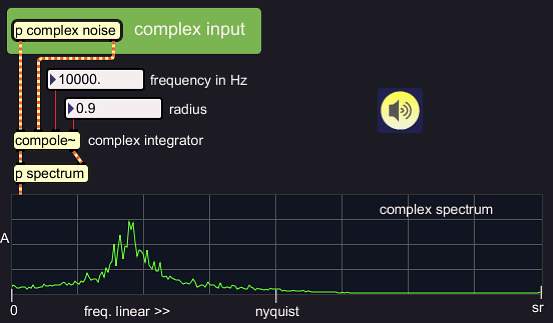 |
The complex
integrator is a bandfilter. Increasing the
radius, for example to 0.999, will make the band narrower:
 |
At high radius
settings, integration can make very narrow bandfilters. But there is a
down side. We have seen how the input must be attenuated according to
radius setting; the normalisation factor in the above example is
0.001. If the input is so much reduced, it must also be the case that
the
integrator needs some time to rise to it's full output level. Even if
the input sound has a fast attack, the filter will not be able to
follow that. Below is an example for radius 0.999. The signal input and
output
of one phase are shown:
 |
With 1-radius input attenuation, the rise time is of the same order
as the decay time, about 25 milliseconds in the above example. This is
best observed
with a square wave input, which is equivalent to a framed DC input:
 |
The
slow rise time in narrow resonating filters is bothersome. Any fast
attack will not make it through
the filter. It would be nice if we could make
that filter work a bit faster. Well? This can be done, actually.
Below, I use three complex filters instead of one. This means, for
every sample moment, three complex multiplications are done instead of
one. It is a way of oversampling. The filter effect of radius 0.999 is
now done with radius 0.99 for each filter.
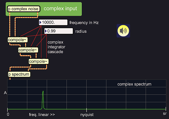 |
Checking the rise time of an input frequency at the filter's center
frequency, shows a much faster rise for the cascade indeed:
 single integrator, radius 0.999 |
 cascade, radius 0.99 |
positive and negative frequencies
I did not tell how I complexified noise before feeding it into
compole~. To be honest, I still have to find out how to make a complex
signal. In the meantime, I use Max/MSP's hilbert~
object which does the necessary 'Hilbert Transform'. It has sets of
allpass
filters with a phase deviation amongst them, 90 degrees for most
frequencies, exept the lowest frequencies and the highest octave.
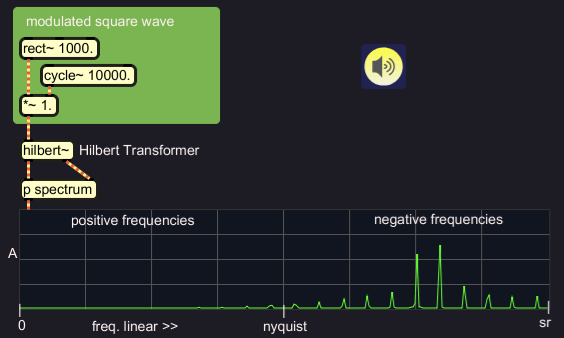
I would think that Hilbert Transform should produce positive
frequencies exclusively.
Below, you can see that hilbert~ produces negative frequencies. This
has confused me many times. Anyway, positive frequencies could be
produced by sign-flipping the imaginary output phase.
 |
Since Hilbert Transform can make complex signals with positive or
negative frequencies exclusively, it is also possible to do both, but
with different content, and mix these down into one complex signal. I
have done that in the example below, to produce a weird demonstration
spectrum where the frequencies above Nyquist are not aliases of those
below Nyquist. The filter radius is at 0 to show the full output:
 |
The complex integrator can distinguish positive from negative
frequencies, so it is now possible to suppress positive frequencies for
example, and let a band of negative frequencies pass through:
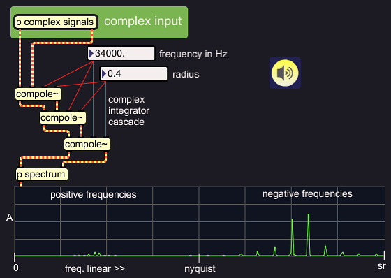 |
At the moment, I have no specific purpose for such single sided
filtering. But I find it so cool, I just wanted to do the illustrations.
It is by the way no problem to feed a real signal in the complex
integrator and filter this:
 |
When we want to hear the filter output, we must choose one of the
filter output phases, since we can not listen to a complex signal. When
a real signal was sent in the filter, there seems to be a difference in
the spectra of the outputs. I set the radius value low so it can be
better perceived. In the first case, the real output is taken:
 |
When the imaginary output is taken, the low frequencies are more
pronounced:
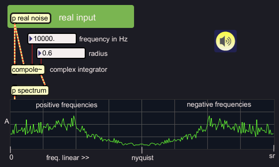 |
This phenomenon is reminiscent of the state variable filter, where
it is exploited to produce hi pass, low pass and band pass from one
filter process. With the complex integrator, the effect can not be
fully exploited. If a real signal is sent in a complex integrator
cascade, the spectral difference between real and imaginary output at
the last filter is gone. How come? The integrators tend to make a real
signal complex. And for complex signals, the complex integrator is a
plain band pass filter at both outputs.
If a complex integrator tends to make a real signal complex, can it
not be used for Hilbert Transform? That is what I had been hoping for.
Unfortunately, it only works well with high radius settings, which
means, narrow filter bands. Here is an example. The circle on the x-y
scope demonstrates the orthogonality of the phases:
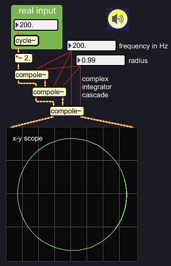 |
At high center frequencies, the radius setting can be lower, and
still a precise complex signal comes out:
|
|
|
It is even possible to transform a 15 KHz signal from real to complex,
that is something which the hilbert~ object can not do.
|
|
the lines are merely interpolations between the points on the circle |
This opens up one interesting perspective. If you would need to do a
constant Q filter bank for any reason, you could have complex outputs
at little extra cost. But what if you want a complex signal without the
filter effect? I have now written so much on complex signals, I really
feel urged to figure out how Hilbert Transform can be done, and do a
solid illustrated documentation of that.