(page still under construction)
Digital reverbs can be built from a dozen delaylines. Techniques for
this were proposed by Manfred Schroeder in the 1960's. There are some
fine open source implementations around, like those based on Freeverb
and Gigaverb. Once you know the basics, it is fairly easy to model a
reverb to your own taste, using a graphical dsp environment like Pure
Data, or in C code.
Room acoustical responses consist of multiple echoes. Most of these
echoes are not audible as such, because they are so densily spaced. To
simulate a dense and diffuse field of echoes, Schroeder proposed this
simple but
brilliant trick: send the output of a feedback delay line in a second
delay line with different periodicity, and the product of that in a
third one, and so on. In this fashion, the echoes are multiplied and
you get a lot of result for little computation. Crucial is, that the
periodicities of the delay lines do not share a common divisor. Their
lengths, expressed in number of samples, must be relatively prime as it
is called. Another essential trait is the flat amplitude spectrum which
must result from each delay line. A regular delayline works like a
combfilter. For the diffusor, the feedback delay lines are accompanied
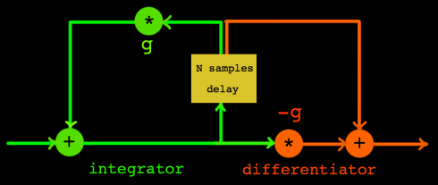
by differentiators to form allpass filters really. Here is the signal
flow of a Schroeder allpass section:
 |
Although the filter has a flat amplitude response, the phase
response is quite a mess. Here is the phase response for the case of
N=2.
 |
(sorry, the main part of this page still has to be written. will be
continued)