
The Fourier filter principle as outlined
on the previous page, was prototyped as a real time process in
Max/MSP, using standard objects. The scheme for this is illustrated
below. At the page bottom is a link where you can
download the patchers.
Max/MSP has the convenient pfft~ object which can load any spectral
subpatch featuring fftin~ and fftout~ objects. Window and overlap, FFT
and IFFT are handled according to user parameter settings, performing
the more efficient 'real FFT' routine if so desired. It is possibly the
easiest doorway to real time spectral processing for a newbie like me.
|
Below is the fourier filter subpatch which is loaded in pfft~. The
pink noise test signal entering the subpatch via the fftin~ object is
already windowed and transformed to real and imaginary spectrum
coefficients. All the objects in the green blocks are there to compute
a filter magnitude spectrum from the FFT bin index numbers. Only at the
end, the input's spectrum coefficients reappear, when they are
multiplied with the filter spectrum.
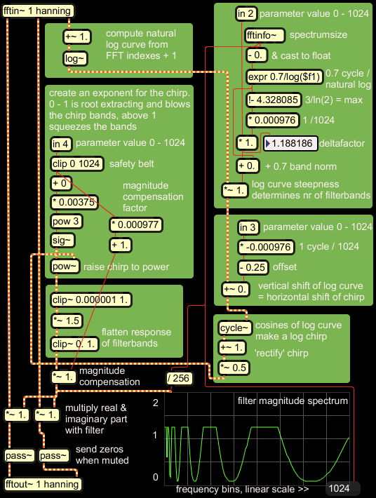 |
Despite the blockwise lay-out, it may not be clear what is going on
exactly, so I will comment the patch step by step.
 |
Start at the top left. A one-channel signal input is
converted into a half-complex spectrum by MSP, with real part,
imaginary
part, and bin index number as the output streams. A logarithmic curve
for each frame
is computed with ln(index+1). |
 |
The FFT size in this case is 2048 samples, which results in
1024 frequency bins.
From this number, the spectrumsize, some parameters are computed in the
top right block, in
order to match the filter magnitude spectrum to the FFT size.
0.7/ln(spectrumsize) computes the minimum 'number' of filterbands that
can be set, it is the floor norm. 3/ln(2) is the ceiling, independent
from spectrumsize, and effectuating third-octave intervals. The floor
is subtracted from the ceiling to compute a slope or deltafactor which
is then multiplied by the user parameter. This result is applied as a
factor on
the initial logarithmic curve, and controls the number of filterbands. |
Why will this 3/ln(2) effectuate third octave intervals, independent
from spectrumsize? Actually this leads to ln(x)*3/ln(2) in the patch.
That is equivalent to 2log(x)*3. While 2log(x)
would do octave intervals, 2log(x)*3 makes a steeper curve,
resulting in a faster sweep and logarithmically dividing octaves into
thirds.
 |
Here, a user parameter of 10 bit value is entered to control a
vertical shift of the logarithmic curve in the x-y plane. This will
later result in an apparent horizontal shift of the sweep, though the
sweep will change shape as well. |
 |
Now at last the logarithmic curve is fed into a cosine lookup
function, resulting in the sweep shape. The sweep is not rectified by
an abs() function here, but scaled and vertically shifted to have
positive values, from 0 till 1. This shape is slightly more
advantageous
for further manipulation. |
 |
By raising the sweep to a
positive power, it's lobes can be widened or narrowed, while keeping
the y values in the 0 - 1 range. Negative powers are dangerous here, as
these result in the muliplicative inverse of numbers smaller than 1,
which can grow very large eventually.
|
I found that the function raising the chirp to a power
can easily generate so called denormal numbers: numbers smaller than
can be represented by the single precision floating point type that is
used for signals in Max/MSP. This will slow down signal processing, as
denormals are handled as exceptions, and lead to thread blocks.
Inserting a clip function here again, reduces the patcher's CPU load
with some 20% of it's initial load.
 |
The sweep is subsequently multiplied by 1.5 and clipped at 1.
The sinusoidal peaks become plateau's, creating filterbands with better
definition. |
 |
Finally, after magnitude compensation, the sweep is a filter
magnitude spectrum, and as such multiplied with real and imaginary
spectrum coefficients of the analysed signal.
|
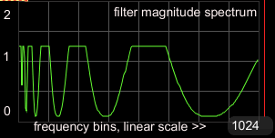 |
I like to check the spectral process with a scope~ object.
This is not the audio signal output, not even the spectrum of it! The
scope is showing the filter characteristics, independent of the signal
input. With a filter complicated like this, a visual check is almost
indispensable. |
download
If you are on Max5, you can download the illustrated patchers and
use them.
|
|
The next page
introduces spectfilter~, a Max/MSP external object based on the
Fourier filter patch with some extra's. You can find downloads there as
well: the object and a demo application.
 fourierfilter.zip, 8 KB, containing fourierfilter.maxpat
+ fourierfiltertest.maxpat, for Max5 users
fourierfilter.zip, 8 KB, containing fourierfilter.maxpat
+ fourierfiltertest.maxpat, for Max5 users