After prototyping a parametric Fourier filter in a Max/MSP patch, I
developed C code for that process, which can be found at the bottom of
this page. Combined with the FFT lib I had
written earlier, it is plugged into one single Max/MSP external object
for further testing, demonstration and musical employment. The object
description is followed by links where you can
download the object or a demo application.
 |
The most significant improvement in the single-object implementation
is a user-controllable FFT size in runtime. Since the
resolution/latency trade-off demands a choice of FFT sizes, according
to programme material, this really was a requirement for the new
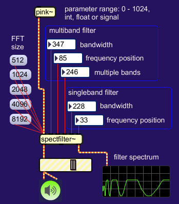
object. In addition to the multiband filter as described on the previous page, the
object has an extra single band filter spectrum, in serial connection.
It's function is to confine the multiband output to a specific region
of the spectrum, if so desired.
In it's simplest form, a patch using the spectfilter~ object would
look like this:
 |
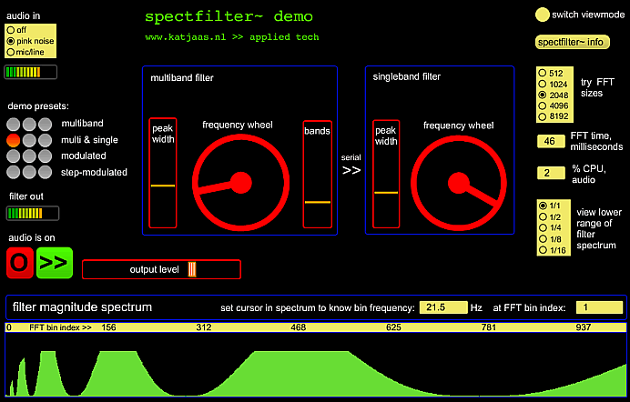
Round the spectfilter~ object I figured a test/demo patch, where the
object is submitted to intense manipulation by modulators. Next to
audio output, the object provides filter spectrum index and y-value,
which in the demo patch are employed for meticulous
visual inspection.
 |
The test input signal is pink noise, but mic/line signals are of
course also enabled, because they were the reason for doing
spectfilter~ in the first place. It turns out that the object can
fluently reflect the weirdest of modulations, extending it's musical
versatility beyond static filter jobs.
In the demo patch, the filter spectrum is dynamically stored into a
named buffer~ object which is
viewed via a waveform~ object. This way, the action of the
filter can be scrutinized in realtime, much more detailed than with a
scope~
object. Settings are available to zoom in on the lower spectrum range,
where things are more critical than higher up. The lowest octave
interval in a discrete spectrum comprises only one FFT bin, one sample,
while the highest octave has half the total spectrum width. Below, the
lowest 1/16 portion of a multiband filter spectrum is represented, for
a 2048 point FFT. The bars represent individual FFT bin values:
 |
Because of the relatively artefact-free resynthesis routine, such
narrow filterbands are not directly problematic, soundwise. The blocky
shapes could make you suspicious, but overlap and proper windowing of
FFT frames will make a smooth filter curve out of this, no matter how
discontinuous it may look. The real hassle is, that filterbands
comprising just one FFT bin or
even less, can no longer correctly represent logarithmic bandwidth and
distribution.
On the page Fourier
Filter, I had made the assessment that logarithmically
distributed separate filterbands can be computed with sufficient
accuracy around bin
30 and higher. From my animated filter spectrum I can now see that this
is indeed the case. My desire to make filterbands extremely narrow
complicates things further. The figure below does not even show the
narrowest filterband setting in spectfilter~, but even here it is clear
that bands
below bin 30 are totally beyond control, due to lack of resolution:
 |
The figure also shows the frequency at bin 30: 646 Hz. (I set the
cursor in the spectrum representation to request the frequency for a
bin). So, everything below that frequency can not properly follow the
logarithmic scheme. For smaller FFT sizes, things are worse, while for
larger FFT sizes it's better.
From these figures, you would say that the spectfilter~ object is
pretty useless in musical practice, uh? I had hoped for a method to
refine a spectrum's resolution by upsampling. Then I met with the
Stretchable but Indivisible Dirichlet Kernel that is the discrete
Fourier transform of a pure sinusoid. Upsampling refines the analysis,
but can not help with sharper filtering. This is the relentless reality
of
spectral filtering. Details on this topic are on the page Windowing & Frequency
Domain Filtering.
Despite this ever-present bottleneck at the low frequencies,
spectral filtering has it's attractions. Specially when you can quickly
choose an appropriate FFT size for the filter job at hand. Below is an
example with two filter lobes, done with 512 point FFT (that is 11
milliseconds at sampling rate 44K1):
 |
If you want to chop your input signal into a couple of dozen peaks,
set a long FFT. Though resizing the FFT can even be done while audio is
on, increasing the size (thus increasing latency) will introduce a
short moment of silence, so you still have to choose an appropriate
moment for the switch. The filter spectrum shown below, done with FFT
size 8192, could not so easily be applied with time domain filters,
certainly not at the price of just a couple percent CPU time:
 |
Such filter settings effectuate specific musical effects. With noisy
input, the filter becomes an instrument in it's own right. And since
the filterspectrum is so easily recomputed, to the point of continuous
modulation, spectfilter~ could be exploited in electronic music
composition indeed. That is not what I made it for, but the lines
between sound processing and synthesis are very thin here.
circular spectrum
In the spectfilter~ object, the filter spectrum is handled as a
periodical phenomenon. This enables a continuous shift of filter peaks
towards the low end or high end of the spectrum without ever reaching a
limit. The peaks just wrap around. The effect is reminiscent of the
famous Shepard tones, but with spectfilter~ the sound can be pure or
diffuse, depending on filter settings.
|
Listen to pink noise filtered with a descending multiband
filter (quicktime player) |
To optimally exploit this unbounded filterband shifting, I had to
find a method which can handle automated shifting and manipulation by
hand simultaneously. Something like a turntable, where you can play
around with speed and direction of the machine. Conveniently, Max/MSP
has a dial object that can do full circles of 360 degrees, with
circular mouse tracking. Ideal for this purpose. For Max fans, here is
a patch and explanation:
 |
The essence is in diffentiating the output values of a sawtooth
modulator wave (phasor~), and with these values, increment/decrement an
integrator which
is built around the graphical interface object. That integrator must
wrap to zero after reaching the maximum parameter value, which is 1023
in my case. This can be realised by using a bitwise-and mask, but only
when the parameter is of unsigned integer type and it's maximum value +
1 is a power of 2. Anti-clockwise wrapping is also possible, if a
constant addition of maximum value + 1 is included in the loop.
The cyclic nature of frequency position applies to multiband and singleband filter in the spectfilter~ object. The other parameters controlling bandwidths and number of filterbands do not wrap around. Parameter values run from 0 till 1023 inclusive and are 'dimensionless', they do not mean anything physical. It is just one of many standard parameter ranges, and my personal favourite.
If you are on Intel Mac, you can play around with spectfilter~
yourself. The object is available, together with the demo patch in the
form of spectfilter~.maxhelp. If you do not own Max/MSP, you can
download spectfilter~demo.app, which has Max Runtime built in. Max 4.6
users could download both zip files, one for the object and the other
for the demo, since spectfilter~.maxhelp was created in Max5 format.
downloads
Part of the spectfilter~ object is a C function that computes a filterspectrum with logarithmic shape and distribution of filter lobes, shown below. It is a refinement of the procedure outlined in the prototype patch on the previous page. The minimum bandwidth is no longer a function of actual FFT size, but a function of the maximum FFT size permitted by the object's buffers. This helps in keeping filter characteristics uniform across FFT sizes. The object incorporates FFT and window/overlap functions which are not shown here. Separate pages on these topics are in the FFT section.
#define LOGMINFFTSIZE 9 // radix 2 logarithm of minimum FFT size used #define LOGMAXFFTSIZE 13 // radix 2 logarithm of maximum FFT size used #define LOGOVERLAP 2 // radix 2 logarithm of FFT overlap factor #define PARRANGE 1024. // user parameter range / maximum value, float #define LIMITEXPONENT -24. // must be a float #define PARFACTOR (1./PARRANGE) void computespectrumbands( typfloat *spectrumbuffer, // filter spectrum is stored for repeated use typfloat *log2table, // table with base 2 logarithms typfloat bandwidth, typfloat freqposition, typfloat bands, unsigned int spectrumsize) { unsigned int n = spectrumsize - 1; typfloat basefactor = 1. / ((float)(LOGMAXFFTSIZE-1)); // fixed base factor typfloat twopi = asin(1.) * 4.; typfloat logcurvefactor, logcurve, freqoffset, logchirp, magnitude; typfloat powbandwidth, subliminal; bandwidth = clipfourierparameter(bandwidth) * PARFACTOR; // clip and scale freqposition = clipfourierparameter(freqposition) * PARFACTOR; bands = clipfourierparameter(bands) * PARFACTOR; magnitude = 1. + bandwidth; // compensation factor powbandwidth = pow((bandwidth * 3), 3); // change response curve subliminal = pow(2, (LIMITEXPONENT / powbandwidth)); logcurvefactor = (((3. - basefactor) * bands) + basefactor) * twopi; freqoffset = (float)log2table[spectrumsize-1] * logcurvefactor; freqposition = -(freqposition * twopi) - freqoffset; *spectrumbuffer++ = 0.; // pass over DC bin log2table++; while(n--) { logcurve = (*log2table++ * logcurvefactor) + freqposition; // compute logarithms logchirp = (cos(logcurve) + 1.) * 0.5; // compute chirp if(logchirp > subliminal) logchirp = pow(logchirp, powbandwidth); else logchirp = 0.; logchirp *= 1.5; // raise the peak(s) if (logchirp > 1.) logchirp = 1.; // clip peak(s) *spectrumbuffer++ = logchirp * magnitude; // apply compensation } } // end of computespectrumbands function definition |